

Do not throw that jitter into the bin !
Abstract
On-board
of
railway
type
vehicles,
Electronic
Brake
Controllers
implementing
Wheel
Slide
Protection
need
to
accurately
monitor
the
signals
from
speed
sensors.
On
said
signals,
a
minimal
amount
of
jitter
is
unavoidable,
and
it
will
always
be
present
due
to
manufacturing
tolerances,
and
various
other
sources
of
background
“mechanical
noise”.
In
a
typical
application
said
minimal
jitter
is
usually
contained
within
±
1%.
Conventional
speed
signals
processing
electronics
disregard
this
modulation
as
merely
one
more
source
of
noise,
being
only
interested
in
the
measurement of the frequency of the speed sensor’s output signal.
On
the
contrary,
we
have
developed
a
technique
which
does
not
disregard
this
source
of
noise,
but
it
instead
includes
specific
means
to
accurately
measure
its
value
(with
microseconds
resolution)
and
periodicity
of
occurrence,
with
the
purpose
to
extract
precious
diagnostics
information about defects of the wheels, bearings, rail track.
C-Sigma
C-Sigma s.r.l. 2024

A
unique
feature
(patented)
allowing
the
detection
of
defects
in
wheels,
bearings,
tracks,
as
well
as
the
monitoring
of
bearings
wear
and
the
detection
of
derailments.
By
a
suitable
processing
of
jitter
on
speed
signals
said
defects
are
promptly
detected.
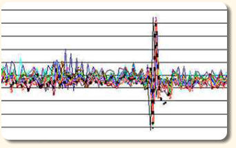
Here
below
is
an
example
of
wheel
flat
detection.
The
figure
shows
the
overlap
of
10
plots
corresponding
to
10
consecutive
complete
wheel
revolutions.
All
plots
indicate
a defect at exactly the same angular position of the wheelset.
When
such
spikes
occur
isolated
(i.e.:
not
correlated
by
complete
wheel
revolutions),
but
on
all
4
axles,
and
with
time
delays
whose
correlation
is
given
by
the
vehicle
speed
and
distance
between
axles,
then
the
probable
cause
is
a
defect
of
the
rail-track
(excessive
gap
or
misalignment).
A
GPS
board
would
then
allow
the
recording
of
the
defect’s
location.
In
case
of
derailment,
the
periodic
“hitting”
of
wheels
over sleepers would also results in clearly detectable spikes.
When
no
defects
are
present,
no
spike
shall
appear.
However,
correlated
plots
can
still
be
recorded
to
monitor
axle’s
bearings
wear.
The
figure below shows the same overlapping of plots as above, but for an axle without defects.
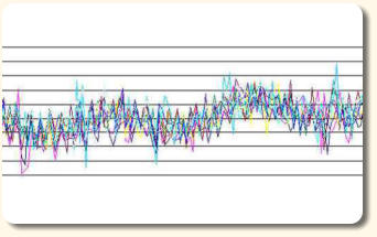
A
pattern,
common
to
all
the
complete
wheels
revolutions
depicted
in
the
graph,
is
clearly
visible.
Its
shape
is
determined
by
the
inherent
eccentricities
and
inaccuracies
resulting
from
standard
machining
and
mounting
techniques.
By
comparing
similar
plots
recorded
at
different
times
(e.g.:
once
a
year,
every
1
million
Km,
etc.),
the
evolution
of
bearings
wear
can
be
monitored
(standard
deviation
would
increase
with
wearing).
An
advantage
of
this
technique
is
that
it
does
not
require
any
additional
external
sensor(always
very
difficult
to
install
in
existing
vehicles),
but it only processes in an innovative way the signals from conventional speed sensors, already present on the wheelset for ABS control.
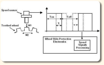
The
reason
why
jitter
noise
contains
information
about
mechanical
shocks
seen
by
the
wheelset,
as
well
as
of
wear
and/or
defects
of
bearings,
can
be
understood
by
studying
the
above
functional
block
diagram.
It
depicts
the
effect
due
to
the
onset
of
the
following
vibration
or disturbance modes:
- Radial Mode M1, which results in small variations of the gap between the sensor’s reading head and the toothed-wheel.
- Peripheral Mode M2, which results in small variations of the relative speed between the sensor’s reading head and the toothed-wheel.
-
Orthogonal
Mode,
along
the
direction
orthogonal
to
M1
and
M2,
but
less
important
because
variations
along
this
direction
do
not
significantly
modify
the
jitter
modulation
(the
corresponding
tooth
dimension
is
larger
that
the
sensor’s
reading
head).
Said
vibration
modes
are,
in
turn,
triggered
by
shocks
and-or
vibrations
due
to
defects
of
the
wheel
(wheel-flats),
and-or
bearings,
and-or
rail
track.
Their
net
effect
on
the
output
signal
is
the
presence
of
jitter,
indicated
with
the
Greek
letter
tau
in
the
above
figure.
Here,
jitter
is
defined
as
a
modulation
of
the
pulse-width
of
the
output
signal.
So
that,
by
watching
for
example
said
output
signal
on
an
oscilloscope,
and
setting
the
trigger point on the rising edge, we would notice continuous small variations of the instant at which the falling edge occurs.
A
minimal
amount
of
jitter
is
unavoidable,
and
it
will
always
be
present
due
to
manufacturing
tolerances,
and
various
other
sources
of
background noise. In a typical application said minimal modulation is usually contained within ± 1%
Conventional
speed
signals
processing
electronics
disregard
this
modulation
as
merely
one
more
source
of
noise,
being
only
interested
in
the
measurement
of
the
frequency
of
the
speed
sensor’s
output
signal.
On
the
contrary, our
technique does
not
disregard
this
source
of
noise,
but
it
includes
specific
means
to
accurately
measure
its
value
(with
microseconds
resolution) and
periodicity
of
occurrence,
with
the specific aim to obtain precious diagnostics information about defects of the wheels, bearings, rail track.
Luca Ghislanzoni